
I have detailed article on modelling the RNZAF Skyhawk here. This explains all the subtleties of the RNZAF aircraft throughout their RNZAF service.
Which Kit(s)?
Any of the A-4E/F kits and TA-4F/J can be used for a RNZAF Skyhawk. For these builds I'm using
- 1/48 A-4K Skyhawk 'RNZAF' - Kit No. 09441 released in 2002. This boxing contains five (5) white metal parts for the upper VOR/ILS antennas, Forward under wing RWR antenna fairings and High Intensity Strobe light. there are all pretty easy to scratch build.

- 1/48 TA-4J Skyhawk - Kit No. 07243 (PT43) released in 2009

Kits marked A-4F only may not be suitable due to the different intakes in those kits. That said the difference in the intake profile is really hard to see. If in doubt take a look at this page . It lists the sprue's in each of the Hasegawa A-4 boxing's. The intake sprue that is correct for the RNZAF aircraft is Sprue J. Some A-4F's (Super Fox) had the up-rated engine of the A-4M and thus those aircraft need the same intake sprue as the A-4M (sprue Q).
Some Comments on the Hasegawa Skyhawk Kits
People often remark that this is one of Hasegawa's better kits. But after building 3 of these now I disagree. It may of been when it was first released but IMHO the fit is far from good in many places. And like many Hasegawa kits of it's vintage the panel lines are for me at least to fine / shallow.
Fit Issues
The main fit issues I've found are as follows:
- The intakes and 'engine front' parts do not meet up
- The RH rear fuselage insert requires filler to match the fuselage contours.
- Inserts for the guns/no gun fairing in the forward wing root to fuselage join don't match wing contours.
- Left hand wing to fuselage join has a gap
- The hump to fuselage join needs some filler.
- The speed brakes don't match the contour of the fuselage when closed. And posing them fully open, unless the aircraft is flying or landing is just plain wrong IMHO (yes I know there are exceptions but they are that, - exceptions). A saving grace is that speed brakes tended to open slightly after shutdown when the hydraulic pressure bled off so you can get away with not making them fit perfectly.
- If you're not using the hump I found the top of the fuselage, under where the hump would be needs a bit of filler to smooth it off.
Other Comments
Some things I've noted
- The panel lines are quite shallow in a lot of places.
- The slat wells on the wings are just plain wrong. There is no step.
- The left main landing gear receptacle is approximately 1 mm to 1.5mm longer than the right one. If you don't reduce this your model will sit left wing high.
- The underside of the tail section (under the hook) pinches up. Luckily there is a panel line here and the Arrester hook covers most of it.
- If doing a A-4F onwards the line that represents the lift spoilers on the upper wing needs to be scribed. This is sometimes not shown on the instructions. Do this before you put the wings together.
- The nose wheel is not molded separately.
- The slat tracks are molded on the wings so get in the way throughout the build.
- The lower edge of the front windscreen has to be glued directly to the kit, there is no lower windscreen frame for the sprue gate to attach too. This can lead to damage tote h clear part.
- The instructions don't tell you to drill out holes for the fuel dump port on the lower wing.
- There are lots of ejector pin marks in annoying places.
- The plastic is very hard which makes scribing difficult.
Sadly all the issues are equally applicable to the newer TA-4 kits despite them being released nine or so years later. As the kits share most of the same sprue's this is understandable.
I will attempt to show I address some of these issues in the following sections.
Aftermarket
Some of the aftermarket I intended to use on this build.
- Quickboost 48 496 - A-4 Skyhawk ejection seat with safety belts
- Quickboost 48 422 - A-4 Gun Barrels
- Quickboost 48 316 - A-4 Refueling Probe
- Quickboost 48 887 - A-4 Skyhawk FOD covers
- Eduard ED 648214 - A-4E/F Skyhawk Wheels Set
- Eduard ED49458 - TA/4J Upgrade set
- Eduard ED 48851 - A-4E/ F upgrade set
- Airscale PE 48MOD - Jet Cockpit PE Set
- Rons Resin Kahu upgrade set
- Steel Beach A-4 Intake blanks
- Phase Hangar Resin 48021 400 Gallon Drop Tanks
- Phase Hangar Resin 48020 A-4/TA-4/ A-7/S-3 300 Gallon Drop Tanks

Kahu Conversion Sets
Since I published this post i there have been two detailed conversion sets released that include all the bits needed to build a post Kahu RNZAF A-4K / TA-4K Skyhawk.
In1/48 scale PhaseHangar Resin is who you need to see.
In 1/32 scale (although not covered by this blog) Barracuda Studios has you covered.
The Wings
One of the major issues with the Hasegawa Skyhawk kit is the slat well moulded onto the leading edge of the wing. This doesn't exist in real life.
If you choose to fix this there are two (2) methods that I've seen used. Either cut the piece out and reposition it, or fill it. Either way you'll be up for some re-scribing. I've not tried the cutting method. On all my builds to date I have filled and sanded to fit using a two part epoxy filler like Magi Scuplt. But in these builds I used plastic strip and various Mr Surfacer fillers to build up the area

This works quite well however as the plastic card is considerably softer than the Hasegawa plastic and a bit of care is needed when re scribing across the transitions between the materials. I used a Galaxy Models rivet tool to redo the fastener detail.
While working on the upper wing pieces the missing lines for the wing spoilers should be scribed.
The wing spoilers were on every aircraft based on the A-4F
onwards. So every F/G/H,/K/M,N,Ku, AR needs it added. As well as every two
seater (so all TA-4's , OA-4 etc). They
were also added the USN A-4L’s , which was based on the A-4C.
They were also on a lot of the A-4E's (AFC 442 is the mod
no.), so check your references. Many of
the foreign variants based on the A-4B and A-4C/A-4L had the system added as
well (so A-4P, Q , L etc). The Argentine A-4C’s
had it added prior to delivery.
In the image below the line in blue is
the existing panel line. The lines in red are the ones you need add for the spoilers.
On the underside of the wings you can see a
cut out on the flaps. This is mark you transfer
to the top wing and scribe from.

In this image the cut out in red is the mark you transfer to the top wing and scribe from.

In the mid 1980's the RNZAF moved the lower Anti Collision light to the right hand side (Refer here) As these are both Kahu aircraft I needed to move it. As it's moulded on the wing piece you simply need to slice it off with a razor saw and glue it in the correct position. On other variants the Anti col stayed on the left as per he kit.
The height of the left hand main gear locating point can also be reduced now. You can clearly how much taller it is in the images below.


For some reason Hasegawa didn't note that the holes for the fuel dump fairing need to be drilled out.

This image shows the changes described above. I also opened up the fuel dump.

The Cockpits
The kit cockpit is pretty good for a pre Kahu (A-4F) from the box and I've had good success just laying the Hasegawa Instrument panel and sidewall decals over the raised detail. But for a post Kahu aircraft there needs to be some significant changes, particularly to the instrument panel. See my other article on Modelling the RNZAF Skyhawk .
Now you really can't see the front instrument panel on completed model so it's debatable how valuable spending time recreating a post Kahu instrument panel is. As the TA-4 aft cockpit will be quite visible with the canopy open I considered it worthwhile spending time on it.
I used various Airscale PE details for the DU's and instrument bezels. These were OK although there are some differences in the sizes of the PE for DU's that are supposed to be the same size.

The kit ejection seat is typical of its era so it worth replacing with a resin seat. There are a few Escapac seats on the market. For me the best are probably the Phase Hangar ones but I had already purchased a number of Quickboost ones which are also nice. None of these actually lay the belts the way we used to but I wasn't going to try and simulate that.
The Quickboot seats require some very minor surgery to fit but nothing worth explaining in detail.

The rails for the seat in the kit cockpit are way to small so I replaced with them with some evergreen strip glued into the proper channel shape.

For the TA-4K I used the PE bits in the Eduard TA-4J upgrade set.


For the TA-4 Cockpit, against my better judgement, I used the PE consoles. I wish I hadn't as they look flat, although once in the model they are definitely better.

I added some details from my reference photos, these included the video recorder box, various levers , a pouch and the oxygen hose. These won't be that visible but I know they are there. The Oxy hoses was made from 0.010 copper wire coiled around some 0.020 thou copper wire. The other details form scrap card.

For the A-4 tub I first tried using the Hasegawa decals over the consoles. This has worked well in the past but this time they just wouldn't settle so in the end I just painted the various knobs etc with a fine brush/ toothpick and Vallejo acrylics. I reckon this looks much better than PE.

On the right side of the cockpit the RNZAF aircraft have a pouch which is used to store the seat pins, HUD cover and the pilots carry on gear. I used some magi sculpt to create these.
Lead shot held in place with white tac and then secured with white glue was used for the nose weight.
Paint used was Gunze MR Color C306 FS 36270. Like a lot of US jets the real cockpit is FS36231 (Mr Color C317) but this looks far to dark in a cockpit in this scale . I find C306 looks better. A wash of thinned oil paint was applied to bring out some of the detail.

The Speed Brakes
Now to the speed brakes. These are designed to be posed open which is not typical - yeah you can find images of aircraft parked with them open but it's not how they are usually configured. They can bleed open a bit when hydraulic power is off so you can see them not flush with the airframe but that is also the exception rather than the norm.
First thing I now do is to nip of the ends of the speedbrake arms along the panel line that is there. You can see in this image that there is a little gap at the front of the speedbrake arms

No surprise, these don't sit flush with the aircraft when fitted so some adjusting its required. The airframe plastic here as some curves that Hasegawa didn't account for in the speed brakes parts (Because they want you have them open) .
I usually try to bend the speed brakes a bit and then fit them to the model so the lower edge is flush. TO make them bend easier a mate, who is a great modeller, suggests putting a cut or two length ways .
I pack the inside with card or even blu tack to get them set right. This helps preserve the RATO attachment panel lines on the speed brakes.


I also drill a hole where the arrestor hook pressure gauge is so I can later paint that while and then use some while glue for a lens. It's the circle on the left hand side under the forward edge of the lower speed brake hinge.

Another task to do at this time is to scribe the drag chute attachment access panel. On the original RNZAF aircraft the hinge is at the top. The ex-RAN aircraft didn’t come with a drag chute but this was added after they came into RNZAF service so was added by the RNZAF. On those aircraft the hinge is at the bottom. Annoyingly I only found this out after I’d finished my build.
Any A-4 with a drag chute will have this panel (e.g. A-4M, A-4AR etc)
Some Kahu Fuselage Additions
Now is the time to open up the hole on the fin for the UHF antenna. Depending on the serial number and time frame this antenna may or may not be here. That said all aircraft ended up with an antenna here. I used these tiny dentists round files for this. The antenna itself is included in the Hasegawa plastic.
You can also open up the holes for the VOR antennas on each side of the top of the vertical fin.

I also added a scratch built radar computer cooling vent. There is no actual hole - I did try but ended up destroying a couple before deciding just to leave the plastic solid.


The Intakes
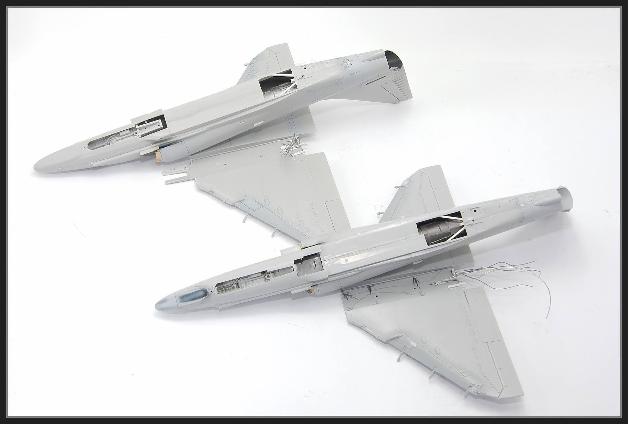
In my experience if you assemble these as per the instructions you'll end up with a step on the inside as the piece that contains the engine face detail is not wide enough for the fuselage. The image below shows the fit before the intake pieces are fitted on the side of the fuselage.

And here is fit with the intake pieces fitted - better but there is still a step in there. You'll also note how badly warped this A-4 kit was .

What I do is cut the piece with the inner intake trunking and engine face in half and attach each half to the fuselage. I will sometimes fill out the cut with some plastic card and glue the circular piece (Generator) on the centre. But often I just attach the circular piece on one side. With the intakes and then the intake lips fitted you can't really see in there anyway.


The main intake pieces also don't fit that well with step being common. I just fill the gap with CA / Talc and hit it with the standing sponges. I then rescribe the lines.
On the single seater there is a reinforcement plate on the main fuselage pieces that needs to be removed so you don't have to be careful with the sanders. A coat of Mr Surfacer will fill the scratches from the sanders. It also pays to paint the intake and intake lips now


Intake Blanks
For these builds all of the above was all a waste of time as I intended to use intake blanks. RNZAF A-4's on the ground nearly always had intake blanks fitted to prevent the ingress of FOD. They were removed when the pilot arrived and fitted immediately after shut down. So if you're doing them on the ground then intake blanks would be my recommendation. Quickboost does a set which are the same as the ones the RNZAF used. The RNZAF also had “locally made ones. Steel Beach also did a set but the Quickboost ones are better.

Another thing to be aware of is that the intakes in the TA-4J and A-4E/F/G/K kits are different sizes. The TA-4 intakes are smaller (they are on a different sprue to the A-4). I found this out as neither the Quickboost nor the Steel beach set fitted on the TA-4. On the actual aircraft I thought the intakes were the same size, see below

The Aft Hell Hole
In the RNZAF the aft hell hole door was always left open until the aircraft was dispatched. I decided to do this. I cut the hell hole door off the lower wing part using a Trumpeter scriber to scribe a line, then a razor saw to remove the part.

This meant I had to simulate something that looks like a engine. You can also see the split intake / engine face here

I also added some detail to the hell hole area on the wing It's not that accurate but no one will look up there anyway.

The aft hell hole door was scratch built using plastic ard and some magi scupt for the pins bag.

On both the TA-4 and A-4, Hasegawa have the fuel or oil dump (part E24) on the left side. On the RNZAF (at least) aircraft they were on the right (see here and here). I don't know if other operators had on the left or right so check your references.

Fill this hole and move E24 to the opposite side.

The Fuselage
Joining the fuselage is pretty straight forward. On the TA-4J Hasegawa have molded a separate nose piece. We can hope this means a OA-4M may come sometime in the future.

The insert at the base of the fin fits reasonably well. The only actual panel line is the forward edge that runs laterally access the fuselage. This is the forward /Aft Fuselage break. The rear edge on the the fin and the longitudinal ones running Forward /Aft can be filled and sanded flush (see here).

There are several tail inserts in the kit, sadly none of them fit particularly well. The RNZAF configuration doesn't have the counter measures dispenser. Once you have fitted the correct insert it’s filler time.
Also on the underside of the tail is a reinforcing strip that runs laterally under the tail. This was only fitted to the ex RAN A-4G / TA-4G aircraft not the RNZAF’s original A-4K/TA-4K's aircraft. Annoyingly I only found this out after I'd finished these builds. The serial numbers of the aircraft I modelled were from the original RNZAF buy and hence shouldn't have the strip.
Even more annoyingly I'd sanded the strip flush and then replaced it with a strip of vinyl tape. I then covered the tape with Mr Surfacer to blend the edge of the tape to the fuselage to better represent the look of them on the real aircraft - Oh well.
The centreline seam aft of the countermeasure inserts to end of the access panels can be left as it was there on the real aircraft (the panels hinged on the centreline). The kit pinches up a bit there but this is hidden by the hook so I don't worry about addressing it.

Wing to Fuselage Fitment
Fitment of the wings to fuselage is generally OK. I do always seem to end up with a little gap on the forward left side, this can be seen below. Clamping helps.


The Upper Communication Antenna
The upper communnications (V/UHF) antenna is in the kit but it doesn't have a the base the real antenna has. I made one out of plastic card. I also adjusted the angle of the antenna to slant it back more as I reckon it looked more accurate that way.

The VOR Antennas
The A-4K boxing of the Hasegawa kit comes with white metal VOR antennas that are quite nice. They have the bulk that the actual antennas have. I used both my sets, one on the A-4K , one on the TA-4K . I scratch built some out of card for future builds.

The Radar Warning Antennas
The A-4K boxing of the Hasegawa kit comes with the white metal radar warning antennas which were fitted under the wings near the wing tips. There would be relatively easy to scratch build. The tail antennas go on the eyebrow panel above the exhaust and come as in the kit.
The Fin Tip
The Kahu modified aircraft had a square fin tip. This is in the kit.
Tacan Antennas
The Drag Chute Cone
The Strobe Light
The Canopy Strap
In Summary
The following two images show much of what I have described above incorporated onto the model.


The Cockpit Glare Shield and HUD

Unless the aircraft was going flying or we needed it for testing the HUD was always covered when it was on the ground. I made a HUD shape out of plastic card and painted it orange.

Unless the aircraft was going flying or we needed it for testing the HUD was always covered when it was on the ground. I made a HUD shape out of plastic card and painted it orange. You’ll have to read on to see this on the finished model as I only fitted at the last minute.
The Ladder
The ladder was pretty much a permanent attachment to the aircraft on the ground.
The steps of the ladder and the top were covered with non-slip surface. I first tried wet and dry paper but wasn’t happy with the result I then remembered this stuff I was given to trial buy a club mate who has an online hobby store (starhobbies.com.au). It is some sort of self-adhesive material with a rough is surface but it is really thin. It was far too sparkly to use raw so I painted it black grey and then flat. It was then cut to size and applied. It seems a good solution for this sort of thing

Finishing
Now that the construction is done it's onto the finishing. There is nothing in the finishing these kits that is specific here to the Skyhawk so the following sections will cover how I finished the two Skyhawks I was building.
Inital Camouflage Colours
I don't often fully prime a kit as I find this can fill up
finer detail. Instead I tend to spot
prime where I've done work.
The camouflage pattern on both kits was marked out with a white
pencil and then freehanded. The basic camouflage
colours were Mr Color 301 - Gray FS36081, Mr. Color 303- Mr. Color - Green
FS34102 and Mr. Color 309 - Green
FS34079. These were applied straight
from the bottle albeit thinned very heavily with Mr Color Levelling Thinner and
sprayed using my 0.2mm Iwata HP-C + Airbrush. Some of the larger areas were touched up
with the trusty Sparmax DH-103.


Next a light gloss coat of Gaianotes Gloss was applied prior
to washes and decaling.


The no step lines were marked out and then painted Tamiya Flat Red.

Decals
Next was an oil wash and then onto the decals. I used the Gekko Graphics sheets for most of the markings. These are a pretty old set but are still often found on ebay for reasonable money. They were released around 2001 (Disclaimer: I supplied some of the details) and cover the single seater RNZAF A-4’s really well. The downsides are they don’t cover the TA-4’s and some the colours (the yellows IMHO) don’t look quite right to my eye. They are printed by Cartogragh and you can read pretty much all the text. They go down reasonably well, but they aren’t as good as Cartogragh printed decals from the past 10 years.

For the TA-4K I used a couple of decals from a Ronin Graphics Australia sheet, specifically the serial numbers, and he Taiaha (spear) on the tail. I chose the Ronin Graphics Taiaha over the Gekko one as it is slightly smaller and just looked better on the model. In real life the stencils for these weren’t exactly precise so they could very in size slightly. Ronin Graphics are an Australian company specialising in Australian subjects, but they do the odd Kiwi sheet as well. Their decals are pretty good, not Cartogragh good and not far from it. Their stuff is done in small runs so it pays to buy them when you get the chance.

Most of the decals went on OK but there was a fair bit of silvering on a couple of the decals from Gekko sheets. Annoyingly they were decals I wanted to use. These are old sheets, printed in the early 2000’s, so I guess it’s understandable.


You may notice that the Sqn crest doesn’t quite look right. Well the A-4K was to be depicted as NZ6201 from No 75 Squadron RNZAF on a particular day in 1993 when it was passing through HMAS Albatross, NSW. Australia. At that time I was working on No 2. Sqn RNZAF and we (for reasons I can't remember) referred to 75 Sqn as the gumboot squadron.
75 Sqn's aircraft had stopped at Nowra for fuel on the way back to New Zealand. Whilst they were there some mates and I took the opportunity to alter the Squadron crest on a number of the aircraft.

The silvering was dealt with some pin pricks and multiple applications of setting solutions. I used Mirco Sol and the Daco Medium and Strong solutions. I even masked some bits and over painted those areas. Unfortunately I didn’t take any images of this stage.
I had no real issues with the decal on the TA-4

From here on in I seem to have lost interest in the camera so I’ll summarise the rest of the build. I spent a bit of time adding wire to the undercarriage legs to simulate the various Hydraulic and electrical cables.
More washes and some weathering with oils were applied. Much of this was done over a coat or two of Gunze GX 113 Flat. Weathering was kept light, mainly because I don't remember the aircraft being particularly dirty or discoloured in the times I worked on them. Areas that were subject to some oil staining were quite often wiped down with a Avtur dampened rag at the end of the day. The aircraft were washed every 56 days.

I loaded the A-4K with Phase Hangar Resin 300 gallon tanks on stations 2 and 4, a single 400 gallon tank on the centreline and 2 LAU 7s from the kit on stations 1 and 5. The 3 tanks made for a heavy model so I pinned the tanks with brass rod to secure them to the racks. Getting the stations sway braces to touch the stores was also time consuming. I also replaced the axle for the Eduard nose gear with a metal pin.

The TA-4 is loaded in a typical 2 Sqn live weapons training load with Eduard Mk 82’s on stations 3 and 5, a Belcher Bits 7 shot CRV 7 rocket pod on station 1 and Phase Hangar Resin 300 gallon tanks on stations 2 and 4.

On both models Remove Before Flight tags from HGW, Eduard and Aerobonus were used. I also made the one for the cockpit from a piece of foil. This was attached to the seat and canopy jettison pins. They were quite long and painted orange.

To see what I'm up to on a regular basis, check out
No comments :
Post a Comment